Isolatie: hun prijzen en isolatiewerken
Maandelijkse energierekeningen lopen genadeloos op. Het is dan ook zeker de moeite waard om je woning goed te isoleren. Hiermee druk je het energieverbruik aanzienlijk naar omlaag, wat je zult terug zien in de kosten die je voor energie moet betalen. Er zijn dus zeker financiële voordelen te behalen. Bovendien draag je eveneens bij aan een verbeterd ecologisch milieu, doordat er minder belasting optreedt. Voor optimale isolatiewerken kun je hier terecht en ontvang de benodigde adviezen en informatie over prijzen voor het isoleren van jouw woning. Lees oook meer over isolatie op www.isolatiewerken-jk.be.
Redenen voor te isoleren
Er zijn verschillende redenen te bedenken waarom isolatiewerken wenselijk of zelfs nodig zijn.
- Een eerste logische reden is uiteraard de daling op de energierekening die ermee te behalen valt. Je houdt de warmte immers langer vast in huis, waardoor de stookkosten dalen.
- Daarnaast draagt het om eenzelfde reden bij aan wooncomfort. Als het koud is buiten, blijft het binnen warmer. Omgekeerd blijft het koeler, als het buiten juist warm is.
- Het werkt bovendien geluiddempend en je draagt bij aan een beter ecologisch milieu.
- In nieuwbouwprojecten is het soms verplicht om voor isolatie te zorgen, om aan maximale warmtedoorlaatbaarheidscriteria te voldoen.
- Een goede isolatie zorgt voor een goede EPC-score, wat je woning aantrekkelijker maakt wanneer je deze zou verkopen.
Vormen van isolatiewerken
Er zijn diverse manieren om een goede isolatie voor je woning te realiseren. Je wilt dat de kou buiten blijft, zonder dat je hiervoor meer hoeft te stoken. De energierekening kan met een optimale isolatie flink dalen, dus het loont om je goed over de verschillende opties te laten informeren om een goede overweging te kunnen maken. Met een EPC-berekening kun je vervolgens uitrekenen hoe energiezuinig je woning is en of je voldoet aan de energie eisen die vanuit overheid aan woningen wordt gesteld. Met gunstige energiepremies kun je je investering snel eruit halen en zo je voordeel behalen op maandelijkse kosten.
Dak isoleren
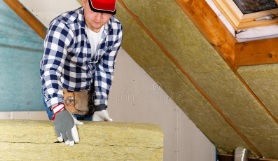
Bespaar tot wel € 530,- op de energierekening door het plaatsen van dakisolatie bij jouw woning. Dit is één van de plekken waar de meeste winst te behalen valt. Je kunt honderden euro’s aan stookkosten besparen als je een goede dakisolatie aanbrengt. Er gaat veel warmte verloren als de daken van je woning matig geïsoleerd zijn. De stookkosten worden ongemerkt hoog, doordat de warmte uit het dak wegtrekt. Zeker door ruimtes vlak onder dak te verwarmen, zul je hierdoor een groot verlies oplopen, als de isolatie niet optimaal is geïnstalleerd. Je kunt tot een derde extra van de verkregen warmte behouden, zodra je zorgt voor een goed geïsoleerd dakoppervlakte.
Lees meer over: dakisolatie prijs advies en tips dak isoleren.
Spouwmuurisolatie
Muurisolatie is een vorm van isolatie die het meest wordt toegepast en zorgt voor een aanzienlijke besparing in energiegebruik. Ook zal het wooncomfort duidelijk beter worden, doordat de warmte beter wordt vastgehouden. Er zijn drie verschillende manieren waarop de muur geïsoleerd kan worden, namelijk binnen in de muur, buitenlangs of via de spouwmuur. De laatste optie is het meest populair, ook doordat dit een stuk goedkoper is dan de andere methodes. Je bespaart er bovendien tot ruim 30% op het gasverbruik mee. Je kunt de spouw opvullen met isolatie als glaswol, EPS- parels of steenwol.
Lees meer over: spouwmuurisolatie: mogelijkheden en gemiddelde prijzen.
Vloerisolatie plaatsen
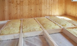
Een andere veel voorkomende plaats waar isolatie kan worden aangebracht, is de vloer. Ook hierbij kan dit zowel bovenlangs als via de onderkant van de vloer worden geplaatst, voor optimaal effect. Als je plafonds of vloeren wilt isoleren, dan is het van belang dat er geen leidingen worden geraakt. Mogelijk zullen er breekwerkzaamheden plaatsvinden om de isolatie juist te plaatsen. De isolatie kan tevens dienen als geluidsdemper tussen twee verdiepingen, waardoor geluiden van buitenaf worden gedempt. Ook geluiden die je binnenshuis maakt worden zo gedempt, zodat je de buren niet stoort. Met vloerisolatie valt veel voordeel te behalen, als dit op de juiste manier wordt geplaatst. Een specialist in isolatiewerken kan je hier uitstekend over adviseren.
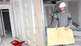
Gebruik van isolatiemateriaal
Je kunt verschillende soorten isolatiemateriaal gebruiken om je woning optimaal te isoleren. De meest gebruikte materialen zijn hierbij glaswol, PIR-platen of PUR-schuim. Je kunt gebruik maken van indelingsmethodes om de isolatie zo goed mogelijk te plaatsen. In de uitvoering kun je ervoor kiezen om isolatiedekens, zoals glaswol of rotswol te gebruiken, vervolgens isolatieplaten als PIR of PUR te plaatsen of te kiezen voor gespoten isolatiewerken met PUR-schuim. Afhankelijk van het doel voor isolatie, kun je kiezen uit thermische isolatie, geluidsisolatie of akoestische isolatiewerken. Als je helder hebt wat je met het isoleren wilt bereiken, zijn er diverse methodes in te zetten om een goede isolatie te realiseren voor je woning.
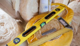
Prijzen voor isolatiewerken
Het plaatsen van isolatie is een verstandige investering om je energieverbruik te verminderen. Het is zeker mogelijk om de kosten die je nu betaalt op langere termijn terug te verdienen, doordat je kunt rekenen op een aanzienlijke energiebesparing. Uiteraard is het daarbij belangrijk om niet onnodig teveel te betalen voor kosten van isolatiewerken.
Factoren die de prijs beïnvloeden
Verschillende factoren bepalen de hoogte van deze kosten.
- Zo wordt deze bepaalt op grond van het te isoleren oppervlak en wijze van isolatie.
- Zijn er breekwerken nodig, dan lopen de kosten meer op.
- Hoe groter de oppervlakte voor het plaatsen van isolatiemateriaal, des te meer voordeel je hier dan echter weer mee kunt behalen.
Voordelige plaatsing van isolatie
Ook de dikte van het isolatiemateriaal zal bijdragen aan de kostenbepaling, waarbij je bij beter materiaal kunt kiezen voor een dunnere isolatielaag. Mogelijk moet er nog een aanvullende afwerkingslaag toegevoegd worden, als muurisolatie langs buiten wordt geplaatst. Een voordeel is wel dat je een deel van de kosten voor isolatiewerken kunt terugverdienen via isolatiepremies. Door offertes bij meerdere specialisten aan te vragen, kun je gemakkelijk prijzen vergelijken en je voordeel doen met het voordeligste aanbod. Zo betaal je nooit teveel voor het plaatsen van isolatiemateriaal en kun je sneller de investering terugverdienen. Zo kom je voor het isoleren van je woning niet voor onaangename verrassingen te staan en zul je er sneller profijt van hebben.
Terugverdienen kosten met isolatiepremies
De investering die je maakt voor het plaatsen van isolatie is terug te verdienen en dankzij de verschillen in premies kun je deze tijdsduur zelfs aanzienlijk inkorten. De netbeheerder betaalt premies voor het plaatsen van dak-, muur- of vloerisolatie. Om in aanmerking te komen voor de genoemde vergoedingen, zul je aan bepaalde voorwaarden moeten voldoen. Dit geldt voor zowel de woning op zich, als het isolatiemateriaal en de facturen die op de isolatiewerken volgen. Elk dak in Vlaanderen zal in 2020 voldoende geïsoleerd moeten zijn, om te voldoen aan de wettelijk eisen. Je kunt een isolatiepremie aanvragen bij je netbeheerder voor het plaatsen van isolatie, om deze werkzaamheden aantrekkelijker te maken.
Offerte aanvragen voor isolatiewerken
Als je isolatie juist geplaatst wilt hebben en wilt profiteren van optimale voordelen om de energierekening omlaag te krijgen, is het verstandig om de isolatiewerken door een erkend isolatiespecialist uit te laten voeren. Zo kun je rekenen op een juiste uitvoering en voldoe je met zekerheid aan de voorwaarden die de overheid voor 2020 stelt. Vraag een offerte aan bij meerdere specialisten, zodat je zeker weet dat je hier de meeste voordeel behaalt en niet onnodig meer betaalt voor dezelfde resultaten. Op die manier kun je de kosten van de investering er tevens sneller uithalen en profiteren van nog meer voordeel.